EN

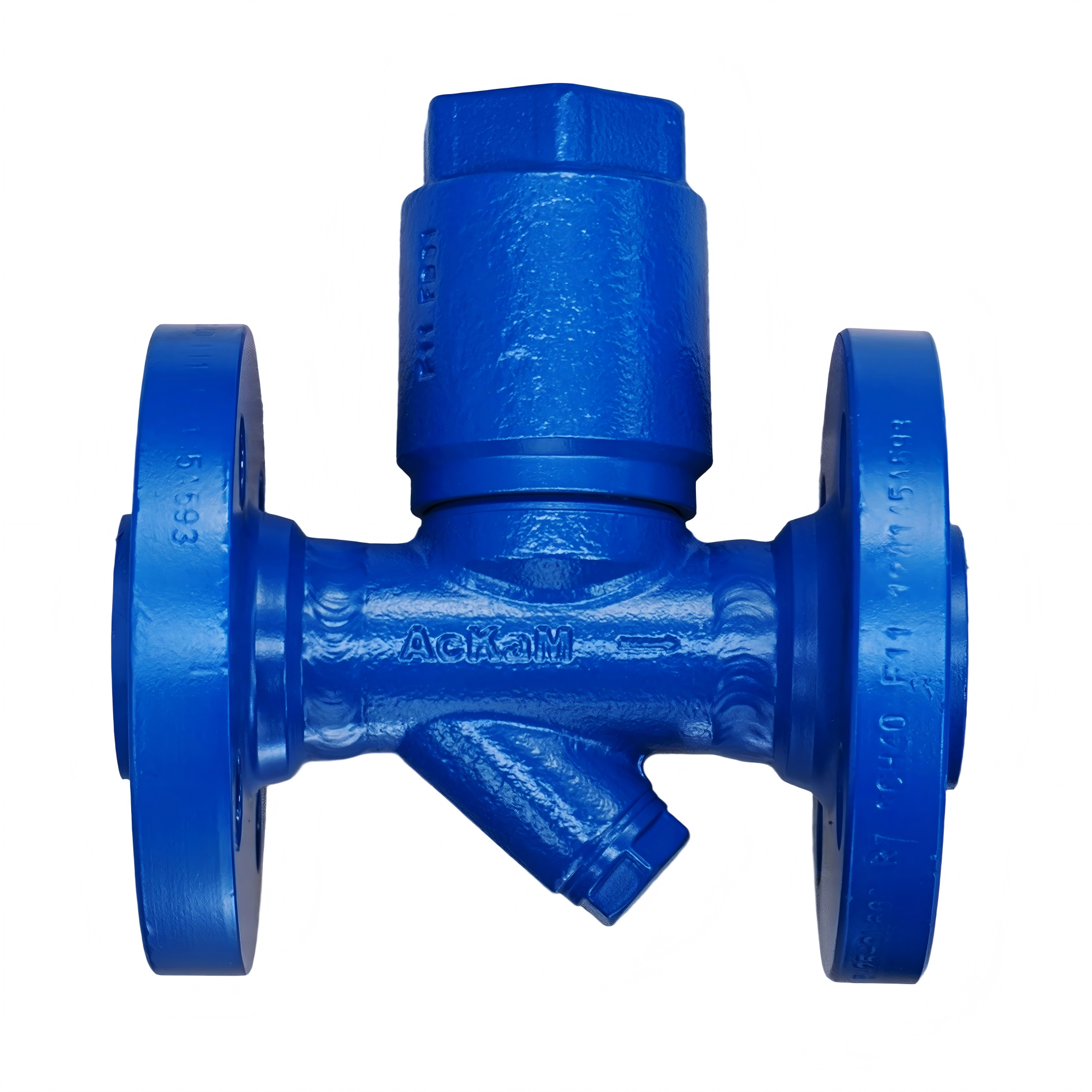
Designing an effective heat tracing system requires careful planning, technical expertise, and a deep understanding of your facility's thermal management needs. Whether you're working with steam or electric applications, a poorly designed heat tracing system can lead to energy waste, equipment failure, and significant operational disruptions. This guide walks you through the essential steps to create a reliable heat tracing system layout that delivers consistent performance and maximizes energy efficiency across your industrial operation.
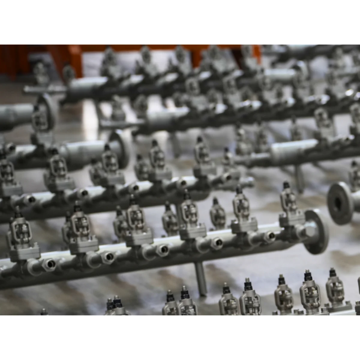
A well-engineered heat tracing system protects pipes, tanks, and instrumentation from freezing, maintains process temperatures, and prevents product degradation in harsh environments. The layout of your heat tracing system directly impacts its effectiveness, longevity, and total cost of ownership. Understanding the fundamental principles of heat tracing system design ensures your installation meets regulatory requirements, performs reliably in extreme conditions, and supports your facility's long-term operational goals.
Understanding Heat Tracing System Fundamentals
Core Principles of Heat Tracing System Design
A heat tracing system operates by applying controlled heat along the length of pipes or equipment to maintain or raise temperatures. The primary function of a heat tracing system is to prevent fluid freezing, maintain viscosity, support chemical reactions, or sustain specific process temperatures. Effective heat tracing system layouts account for pipe diameter, insulation thickness, ambient conditions, and the specific thermal requirements of your fluid or process.
The two main technologies for your heat tracing system are steam tracing and electric tracing. Steam heat tracing systems use heated steam flowing through small-diameter tubes parallel to the process line, while electric heat tracing systems rely on resistance heating elements. Your choice between steam and electric for your heat tracing system depends on available utilities, energy costs, temperature requirements, and maintenance capabilities at your facility.
Heat Loss Calculation and Thermal Requirements
Before you design your heat tracing system, calculate the heat loss from exposed pipes under worst-case conditions. Heat loss depends on pipe size, fluid temperature, ambient temperature, wind speed, and insulation quality. A properly sized heat tracing system must deliver enough thermal energy to offset these losses and maintain target process temperatures. Undersizing your heat tracing system results in inadequate temperature control, while oversizing increases energy consumption and operational costs unnecessarily.
Most industrial facilities use thermal modeling software to predict heat loss and verify that their planned heat tracing system will perform adequately. This analysis guides decisions about tracing line diameter, spacing, operating pressure, and control strategies for your heat tracing system. Accurate heat loss calculations prevent costly retrofits and ensure your heat tracing system functions reliably from day one.
Designing Your Heat Tracing System Layout
Route Planning and Physical Layout Strategy
The physical routing of your heat tracing system should follow the process line as closely as possible, minimizing distance and ensuring even heat distribution along the entire length. Lay out your heat tracing system to avoid sharp bends, congested areas where access is limited, and zones susceptible to mechanical damage. Your heat tracing system layout must allow space for maintenance personnel to inspect, clean, and replace components when necessary.
When designing your heat tracing system around multiple pipe runs, group similar temperature requirements together to simplify control valve arrangements and reduce the number of separate circuits. For complex facilities, create a detailed isometric drawing showing the exact route of your heat tracing system, identifying start points, end points, measurement locations, and control zones. This visual reference prevents installation errors and helps maintenance teams understand the layout of your heat tracing system during troubleshooting.
Insulation and Protection Strategies
Insulation is critical to the efficiency and performance of your heat tracing system. Inadequate insulation forces your heat tracing system to work harder, consuming more energy and struggling to maintain temperatures during extreme cold. Most facilities wrap their heat tracing system with closed-cell foam, fiberglass, or mineral wool insulation rated for the maximum operating temperature of your heat tracing system.
The insulation thickness for your heat tracing system typically ranges from two to four inches, depending on ambient conditions and energy economics. Outdoor installations in arctic climates require thicker insulation and more powerful heat tracing system capacity than mild climates. Jacketing your heat tracing system with protective vapor barrier material prevents moisture infiltration, which degrades insulation and encourages corrosion under the surface of your heat tracing system.
Control and Monitoring Systems
Modern heat tracing system designs include automatic temperature controls that respond to ambient conditions and process feedback. A well-designed heat tracing system uses thermostats, sensors, and proportional control valves to deliver just enough heat to maintain target temperatures without energy waste. Many industrial facilities integrate their heat tracing system with building automation systems or SCADA platforms for remote monitoring and data logging.
Temperature sensors placed strategically along your heat tracing system provide feedback for control decisions and alert operators to potential failures. A reliable heat tracing system includes redundant sensors at critical locations to ensure continued operation if a single sensor fails. Alarms triggered by low outlet temperatures or high power consumption help maintenance teams identify problems with your heat tracing system before complete failure occurs.
Installation and Commissioning Practices
Proper Installation Techniques for Heat Tracing System Success
Installation quality directly determines how well your heat tracing system performs over its service life. Secure the tracing tubes or cables to the process line using thermal contact cement, adhesive-backed straps, or mechanical fasteners designed for your heat tracing system type. Ensure the tracing line maintains full contact with the pipe surface along the entire length of your heat tracing system to maximize heat transfer efficiency.
For your heat tracing system installation, seal all open ends of the tracing tubing and inspect connections for leaks before insulating. Apply insulation in continuous layers without gaps or voids that could compromise the thermal performance of your heat tracing system. When installing your heat tracing system with multiple parallel trace lines on the same process pipe, space them symmetrically to distribute heat evenly across the process line perimeter.
Testing and Commissioning Your Heat Tracing System
Before bringing your heat tracing system into full operation, conduct pressure tests on steam systems and electrical continuity tests on electric systems. Run your heat tracing system at full capacity for several hours while monitoring temperatures at multiple points along the line to verify uniform heating. Document baseline performance data for your heat tracing system so maintenance teams can compare future readings to identify deterioration or component failure.
Commission your heat tracing system gradually, allowing time for the system to reach steady-state conditions at each power level. This gradual approach reveals control logic issues, sensor placement problems, or insulation defects in your heat tracing system before they cause operational emergencies. Train facility staff on operating procedures specific to your heat tracing system, including normal startup sequences, alarm responses, and seasonal adjustment protocols.
FAQ
What is the minimum insulation thickness required for a heat tracing system?
The minimum insulation thickness for your heat tracing system depends on ambient temperature, pipe diameter, and energy economics. In temperate climates, two inches of foam insulation often suffices, while arctic applications demand four inches or more. Consult thermal calculations specific to your heat tracing system location and fluid requirements to determine the optimal insulation thickness for your installation.
How often should a heat tracing system be inspected and maintained?
A heat tracing system should be inspected at least annually before winter heating seasons and checked monthly during peak operating months. Look for signs of insulation damage, corrosion, leaks, or sensor malfunction that could compromise your heat tracing system performance. Most facilities establish a preventive maintenance schedule for their heat tracing system components, including thermostats, valves, and trace tubing, to prevent unexpected failures.
Can a heat tracing system be retrofitted to an existing pipe installation?
Yes, a heat tracing system can be retrofitted to existing pipes, though the process requires careful planning and temporary shutdown of the process line. Retrofitting your heat tracing system is often more labor-intensive than installing during initial construction, but it remains cost-effective when existing pipe temperatures cannot be maintained through other means. Work with experienced contractors to design your retrofit heat tracing system layout that minimizes disruption and maximizes performance within existing spatial constraints.