
Selecting the appropriate control valve for industrial process optimization requires careful consideration of multiple technical and operational factors. Modern manufacturing facilities depend heavily on precise flow control mechanisms to maintain optimal performance, reduce energy consumption, and ensure consistent product quality. A well-chosen control valve serves as the critical interface between process control systems and physical flow streams, directly impacting overall system efficiency and reliability. Understanding the fundamental principles behind control valve selection enables engineers and facility managers to make informed decisions that enhance long-term operational success.
Understanding Control Valve Fundamentals
Basic Operating Principles
Every control valve operates on the principle of variable flow restriction, where the valve opening adjusts automatically or manually to regulate fluid flow rates. The control valve receives signals from process control systems, typically in the form of pneumatic, hydraulic, or electronic inputs. These signals correspond to desired flow rates, pressure levels, or temperature requirements within the process system. The valve's internal components, including the seat, plug, and actuator mechanism, work together to provide precise flow modulation. Understanding these fundamental operating principles helps engineers select control valves that align with specific process requirements and control system architectures.
The relationship between valve position and flow rate defines the control valve's inherent flow characteristic, which can be linear, equal percentage, or quick opening. Linear characteristics provide uniform flow changes across the full range of valve positions, making them suitable for applications requiring consistent flow increments. Equal percentage characteristics offer smaller flow changes at low openings and larger changes at high openings, providing better control stability in varying process conditions. Quick opening characteristics deliver maximum flow with minimal valve movement, ideal for on-off service applications rather than precise modulating control.
Key Performance Parameters
Control valve performance depends on several critical parameters that must be evaluated during the selection process. Flow coefficient (Cv) represents the valve's flow capacity and indicates the gallons per minute of water that will flow through the control valve at a one-pound-per-square-inch pressure drop. Rangeability defines the ratio between maximum and minimum controllable flow rates, with higher rangeability values indicating better turndown capabilities. Response time measures how quickly the control valve can change positions in response to control signals, directly affecting system stability and control accuracy.
Pressure drop considerations significantly influence control valve sizing and selection decisions. The available pressure drop across the control valve must provide sufficient energy to achieve desired flow rates while maintaining stable operation. Insufficient pressure drop can lead to poor control performance and reduced rangeability, while excessive pressure drop wastes energy and may cause cavitation or flashing in liquid applications. Proper sizing calculations ensure optimal pressure drop utilization and prevent operational problems that can compromise process performance and equipment longevity.
Critical Selection Criteria
Process Fluid Characteristics
The properties of process fluids directly impact control valve material selection, sizing calculations, and operational considerations. Corrosive fluids require control valve bodies and trim components manufactured from corrosion-resistant materials such as stainless steel, exotic alloys, or specialized coatings. Abrasive fluids containing solid particles necessitate hardened trim materials and specific flow path designs that minimize erosion damage. High-temperature applications demand control valve materials with appropriate thermal expansion characteristics and temperature ratings that exceed normal operating conditions with adequate safety margins.
Fluid viscosity affects flow calculations and valve sizing procedures, as viscous fluids require different correction factors compared to low-viscosity applications. Multi-phase fluids containing gas-liquid mixtures present unique challenges for control valve selection, requiring specialized sizing methods and potentially custom valve designs. Chemical compatibility between process fluids and valve materials must be thoroughly evaluated to prevent degradation, contamination, or safety hazards. Understanding these fluid characteristics enables engineers to select control valves with appropriate materials, designs, and specifications for reliable long-term service.
Operating Conditions and Environment
Operating pressure and temperature ranges define the fundamental design requirements for control valve selection. High-pressure applications require control valve bodies with adequate pressure ratings and robust construction to withstand system pressures with appropriate safety factors. Temperature extremes affect material properties, sealing effectiveness, and thermal expansion considerations that influence valve design and installation requirements. Ambient environmental conditions, including humidity, chemical exposure, and temperature variations, impact actuator selection and protective equipment requirements.
Installation space constraints often limit control valve size and configuration options, requiring compact designs or specialized mounting arrangements. Accessibility requirements for maintenance and repair activities influence valve selection and installation planning. Electrical classification requirements in hazardous areas necessitate intrinsically safe or explosion-proof actuator designs with appropriate certifications. These environmental and operational factors significantly influence the control valve selection process and must be carefully evaluated to ensure safe and reliable operation.
Valve Types and Applications
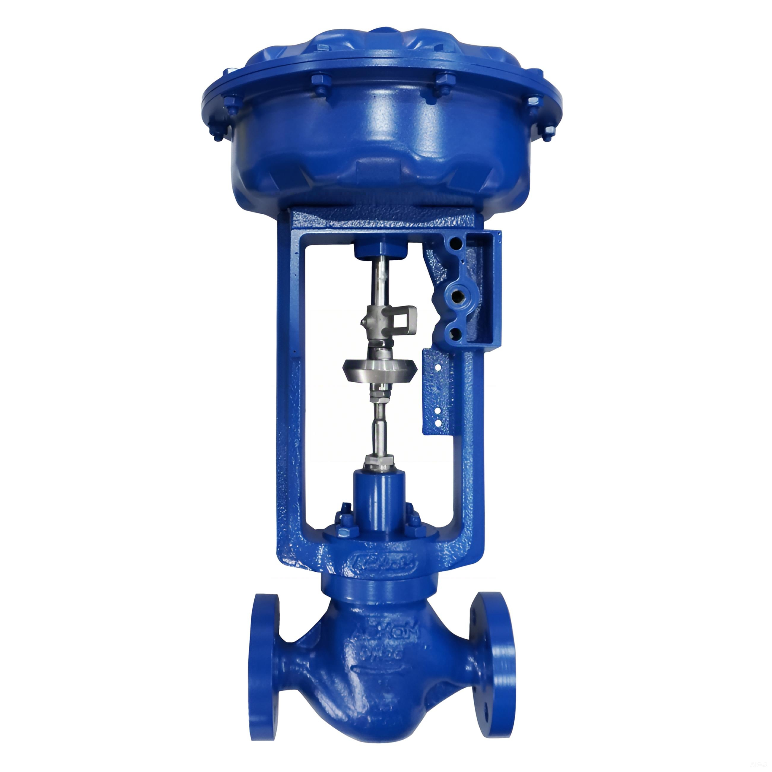
Globe Valve Configurations
Globe-style control valves represent the most common configuration for modulating flow control applications across diverse industries. Single-seat globe valves provide excellent shutoff capabilities and precise flow control characteristics, making them suitable for applications requiring tight closure and accurate flow modulation. Double-seat globe valves offer reduced actuator force requirements due to pressure balancing effects, enabling larger valve sizes with smaller actuators. Three-way globe valves provide mixing or diverting functionality for temperature control and blending applications where multiple fluid streams require coordination.
Cage-guided globe valves incorporate cylindrical cages that guide the valve plug and provide multiple flow paths for enhanced capacity and reduced noise generation. The cage design allows for easy trim changes to modify flow characteristics or capacity without replacing the entire control valve assembly. Anti-cavitation trim designs utilize specialized flow paths that gradually reduce pressure and prevent cavitation damage in liquid applications. These advanced globe valve configurations provide solutions for challenging applications while maintaining the fundamental advantages of proven globe valve technology.
Rotary Valve Designs
Rotary control valves utilize quarter-turn operation and offer advantages in terms of space efficiency, lower cost, and reduced maintenance requirements compared to globe valves. Ball valves provide excellent flow capacity and minimal pressure drop characteristics, making them suitable for high-flow applications with limited available pressure drop. Butterfly valves offer compact designs and lightweight construction for large-diameter applications where space and weight considerations are important. Eccentric plug valves combine the sealing advantages of globe valves with the space efficiency of rotary designs.
Rotary valve actuators typically require less air consumption and provide faster response times compared to linear actuators used with globe valves. However, rotary control valve designs may have limitations in terms of rangeability and precision compared to well-designed globe valve configurations. The selection between rotary and linear valve types depends on specific application requirements, including flow capacity, rangeability, pressure drop limitations, and space constraints. Understanding the advantages and limitations of different rotary control valve designs enables engineers to make appropriate selections for diverse process applications.
Actuator Selection and Integration
Pneumatic Actuator Systems
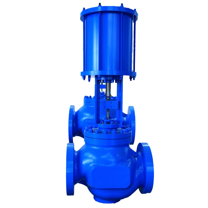
Pneumatic actuators represent the most widely used actuation method for industrial control valve applications due to their reliability, simplicity, and intrinsic safety characteristics. Spring-and-diaphragm actuators provide fail-safe operation by automatically positioning the control valve to a predetermined safe position upon loss of air supply. Piston actuators generate higher forces and offer more precise positioning capabilities compared to diaphragm designs, making them suitable for larger valves or high-pressure applications. Double-acting pneumatic actuators provide bidirectional force capability and can maintain any position without continuous air supply.
Air supply requirements for pneumatic actuators must consider quality, pressure, and flow rate specifications to ensure reliable operation. Instrument air systems typically provide clean, dry air at 20 psig supply pressure with adequate flow capacity to meet actuator response time requirements. Positioners and other pneumatic accessories enhance control valve performance by improving positioning accuracy, response time, and diagnostic capabilities. Proper sizing of pneumatic actuators requires consideration of required thrust or torque, available air supply pressure, and desired response characteristics.
Electric and Hydraulic Alternatives
Electric actuators offer precise positioning control and integration capabilities with digital control systems, eliminating the need for compressed air systems in some applications. Motor-operated actuators provide high-force capabilities and can be equipped with sophisticated control electronics for advanced positioning and diagnostic functions. Electric actuators typically require more complex control systems and may have limitations in hazardous area applications without appropriate electrical protection. However, they offer advantages in terms of precision, repeatability, and integration with modern digital control platforms.
Hydraulic actuators generate extremely high forces and fast response times, making them suitable for large control valve applications or emergency shutdown services. The complexity and cost of hydraulic systems typically limit their use to specialized applications where pneumatic or electric alternatives cannot meet performance requirements. Hydraulic actuator systems require careful consideration of fluid compatibility, environmental impact, and maintenance requirements. The selection of actuator technology depends on application requirements, available utilities, environmental considerations, and integration requirements with existing control systems.
Sizing and Performance Calculations
Flow Coefficient Determination
Accurate control valve sizing requires precise calculation of flow coefficients based on process fluid properties, operating conditions, and desired flow rates. The fundamental sizing equation relates flow rate, pressure drop, fluid density, and flow coefficient through established relationships defined by industry standards. Liquid applications utilize different sizing equations compared to gas or steam services, with specific corrections for viscosity, critical pressure ratios, and compressibility effects. Proper sizing ensures adequate control valve capacity while avoiding oversizing that can lead to poor control performance and unnecessary cost.
Cavitation and flashing considerations significantly impact control valve sizing calculations for liquid applications. Cavitation occurs when local pressure drops below fluid vapor pressure, creating vapor bubbles that collapse downstream and cause noise, vibration, and erosion damage. Choked flow conditions limit maximum achievable flow rates regardless of additional pressure drop increases. Sizing calculations must account for these phenomena to select appropriate control valve designs and predict actual performance characteristics under various operating conditions.
Rangeability and Turndown Requirements
Control valve rangeability defines the ratio between maximum and minimum controllable flow rates, directly impacting process control capability and flexibility. High-rangeability applications require control valves with linear installed characteristics and stable operation at low flow rates. Turndown requirements depend on process variability and control system requirements, with typical industrial applications requiring rangeability ratios between 20:1 and 50:1. Advanced control valve designs can achieve rangeability ratios exceeding 100:1 through specialized trim designs and precision manufacturing techniques.
Installed flow characteristics differ from inherent characteristics due to system pressure drop effects and piping configurations. High system pressure drops tend to linearize equal percentage control valve characteristics, while low system pressure drops may result in quick opening installed characteristics. Proper sizing calculations consider both inherent valve characteristics and system effects to predict actual installed performance. Understanding these relationships enables engineers to select control valve characteristics that provide optimal control performance across the full range of operating conditions.
Installation and Maintenance Considerations
Piping and System Integration
Proper control valve installation requires careful attention to piping design, support structures, and accessibility requirements that affect long-term performance and maintenance activities. Straight pipe runs upstream and downstream of the control valve help establish stable flow profiles and improve sizing accuracy. Adequate pipe support prevents mechanical stress transmission to the control valve body and actuator components. Isolation valves and bypass arrangements facilitate maintenance activities and provide operational flexibility for process control during valve service activities.
Control valve orientation affects actuator performance, accessibility, and drainage considerations in various installation configurations. Vertical installations may require special actuator mounting arrangements and consideration of fluid column effects on force calculations. Horizontal installations typically provide better accessibility but may require additional support for large valve and actuator assemblies. Proper installation practices include attention to electrical connections, pneumatic tubing routes, and protection from environmental exposure that could affect control valve performance and reliability.
Preventive Maintenance Programs
Systematic preventive maintenance programs significantly extend control valve service life and maintain optimal performance characteristics throughout the equipment lifecycle. Regular inspection schedules should include visual examination of actuator components, pneumatic connections, and valve body conditions. Diagnostic testing using portable instruments can detect developing problems before they result in process disruptions or equipment failures. Performance monitoring through control system data analysis helps identify gradual degradation trends and optimize maintenance timing.
Spare parts inventory management ensures availability of critical components for emergency repairs and scheduled maintenance activities. Common wear items include valve seats, packing materials, diaphragms, and positioner components that require periodic replacement based on service conditions and operating hours. Proper documentation of maintenance activities and performance trends provides valuable information for future control valve selections and helps optimize maintenance intervals. Training programs for maintenance personnel ensure proper procedures and safety practices during control valve service activities.
FAQ
What factors determine the appropriate control valve size for a specific application?
Control valve sizing depends on maximum required flow rate, available pressure drop, fluid properties, and rangeability requirements. Engineers must calculate the flow coefficient (Cv) using standard sizing equations that account for liquid or gas service conditions. Proper sizing typically requires the control valve to operate between 70-90% open at maximum flow conditions to maintain good control characteristics and provide capacity margin for future requirements. Oversized valves result in poor control performance at low flows, while undersized valves cannot achieve required flow rates.
How do I select between pneumatic and electric actuators for industrial applications?
Pneumatic actuators offer simplicity, reliability, and intrinsic safety advantages for most industrial control valve applications, particularly in hazardous environments. Electric actuators provide superior positioning accuracy and integration capabilities with digital control systems but require more complex installation and protection in classified areas. The selection depends on available utilities, precision requirements, environmental conditions, and control system architecture. Pneumatic actuators typically cost less initially and require simpler maintenance procedures compared to electric alternatives.
What maintenance activities are essential for optimal control valve performance?
Essential maintenance includes regular inspection of packing integrity, actuator calibration, and positioner adjustment to maintain accurate positioning. Periodic performance testing should verify control valve capacity, response time, and shutoff capability according to process requirements. Predictive maintenance techniques using vibration analysis and partial stroke testing can identify developing problems before failures occur. Documentation of maintenance activities and performance trends helps optimize service intervals and plan future equipment replacements or upgrades.
How do process fluid properties affect control valve material selection?
Corrosive fluids require stainless steel or exotic alloy construction with appropriate corrosion resistance ratings for specific chemical environments. High-temperature applications need materials with adequate temperature ratings and thermal expansion characteristics to prevent binding or leakage. Abrasive services require hardened trim materials and designs that minimize erosion damage to seating surfaces. Chemical compatibility testing ensures selected materials will not degrade or contaminate process fluids over the expected service life of the control valve installation.
Table of Contents
- Understanding Control Valve Fundamentals
- Critical Selection Criteria
- Valve Types and Applications
- Actuator Selection and Integration
- Sizing and Performance Calculations
- Installation and Maintenance Considerations
-
FAQ
- What factors determine the appropriate control valve size for a specific application?
- How do I select between pneumatic and electric actuators for industrial applications?
- What maintenance activities are essential for optimal control valve performance?
- How do process fluid properties affect control valve material selection?