EN

A condensate collection station represents one of the most critical infrastructure components in industrial steam systems, yet many facilities underestimate its importance in achieving operational efficiency. When steam condenses back into liquid water, this valuable resource contains significant residual heat energy that can be recovered and reused throughout your facility. Designing a condensate collection station that maximizes this recovery potential requires understanding system dynamics, material selection, and integration strategies that align with your specific operational demands.
The efficiency gains from a properly engineered condensate collection station extend beyond simple heat recovery; they encompass system reliability, maintenance cost reduction, and environmental sustainability. Industrial operators who invest in optimizing their condensate collection station design often report improved energy efficiency ratings, reduced operational costs, and enhanced equipment lifespan. This comprehensive guide walks you through the essential design principles, technical considerations, and best practices needed to build a condensate collection station that performs at maximum efficiency.
Core Design Principles for Your Condensate Collection Station
Understanding System Architecture and Flow Dynamics
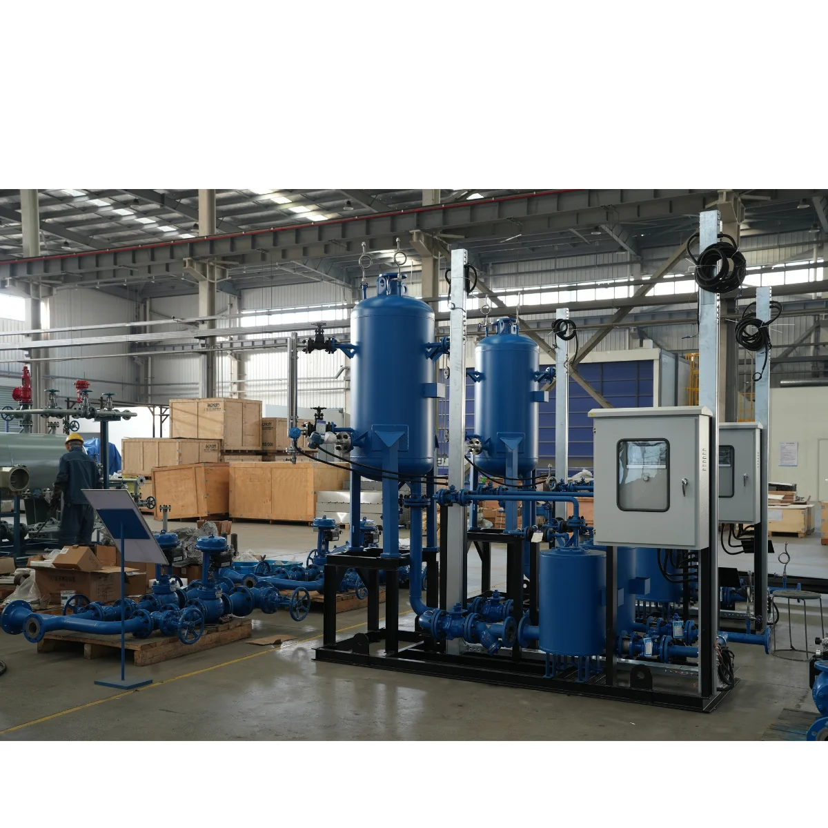
The foundation of an efficient condensate collection station begins with understanding how condensate flows through your system. When steam transfers heat to a process, it transforms into condensate that must be efficiently gathered, filtered, and either returned to the boiler or sent for secondary use. A well-designed condensate collection station incorporates multiple collection points that funnel condensate into a central tank where separation of air, oil, and other contaminants occurs. The tank size, inlet configuration, and outlet placement directly influence how effectively your condensate collection station can manage thermal shock, prevent water hammer, and maintain consistent pressure throughout the circuit.
Gravity flow remains the most reliable method for moving condensate through your condensate collection station network, as it eliminates dependence on mechanical pumps in early collection stages. However, many industrial applications require mechanical assistance, which is why choosing the right pumping technology for your condensate collection station becomes essential. The pump must handle saturated, hot water without cavitation while maintaining consistent flow rates even as system demands fluctuate. By integrating condensate collection station equipment that accounts for these dynamics, you establish a foundation for reliable long-term operation.
Thermal Management and Heat Recovery Integration
Heat retention within your condensate collection station directly impacts recovery efficiency and downstream system performance. Condensate emerging from steam-using equipment can reach temperatures of 160–180°F, representing significant thermal energy that dissipates if not captured. Proper insulation around all condensate collection station piping, tanks, and return lines minimizes heat loss during transport back to the boiler or preheating stage. Additionally, designing your condensate collection station with heat exchanger integration allows you to transfer remaining thermal energy to incoming process water, significantly reducing overall facility energy consumption.
Flash steam generation must be carefully managed within your condensate collection station design, as pressure drops cause instantaneous vaporization of a portion of the condensate. Rather than venting this flash steam to atmosphere, modern condensate collection station designs capture it through flash tanks and secondary recovery systems. This captured energy can be redirected to low-pressure heating applications, representing a substantial efficiency gain. The thermal management approach you choose for your condensate collection station determines whether energy recovery reaches 60–70% or merely 20–30% of available potential.
Technical Specifications and Component Selection
Tank Sizing and Material Considerations
Selecting the correct tank capacity for your condensate collection station requires analyzing peak condensate generation rates, dwell time requirements, and system pressure classifications. Industry standards recommend that your condensate collection station tank volume accommodate at least 5–10 minutes of maximum condensate flow, allowing time for sediment settlement and air release. Undersized tanks in a condensate collection station create backpressure that reduces process efficiency and can cause equipment damage, while oversized tanks consume valuable facility space and delay condensate return. Material selection for your condensate collection station tank depends on water chemistry; carbon steel works for neutral condensate, but stainless steel becomes necessary when condensate contains acidic or corrosive elements.
Pressure rating represents another critical specification for your condensate collection station tank design. Most industrial condensate collection station installations operate at 15–25 PSI, but your specific steam system requirements may demand higher ratings. The tank must withstand not only normal operating pressure but also transient spikes from water hammer or rapid condensate surges. Proper venting design for your condensate collection station prevents overpressurization, while internal baffles and diffusers calm incoming condensate and facilitate separation of entrained gases and oils.
Filtration and Quality Control Systems
Condensate quality directly affects how efficiently your condensate collection station system operates and how long equipment survives. Suspended solids, oil residues, and dissolved minerals in condensate returning to the boiler accelerate corrosion and reduce heat transfer efficiency. Your condensate collection station design must incorporate multiple filtration stages to remove particles larger than 100 microns at minimum. Coarse strainers placed at condensate inlets catch large debris, while dedicated cartridge filters within your condensate collection station structure provide secondary polishing before water returns to the boiler feed pump.
Oil separation technology within your condensate collection station protects both downstream equipment and process quality. Industrial steam systems often experience minor oil carryover from compressor lubrication or process contamination, necessitating oil-water separation capability in your condensate collection station design. Coalescing filters or simple gravity separation chambers integrated into your condensate collection station structure remove these contaminants before condensate reaches treatment or reuse points. Regular monitoring and maintenance of your condensate collection station filtration components ensures sustained performance and prevents costly equipment failures.
Operational Optimization and System Integration
Pump Selection and Control Strategy
The pump you select for your condensate collection station system must handle condensate's unique characteristics: high temperature, tendency toward vapor formation, and sensitivity to inlet pressure conditions. Centrifugal pumps designed specifically for condensate duty incorporate larger impeller clearances and specialized materials that prevent cavitation common in standard pump models. Your condensate collection station pump must maintain positive inlet pressure by positioning the tank above the pump suction, or by installing a small pressurizing vessel in your condensate collection station design. Variable frequency drive technology allows your condensate collection station pump to adjust output based on actual condensate generation, reducing energy waste during periods of lower demand.
Control logic within your condensate collection station system should automatically respond to tank level fluctuations, preventing overflow while maintaining sufficient residence time for air and contaminant release. Float switches or level sensors in your condensate collection station tank activate the pump when levels reach predetermined heights and shut it down when the tank approaches empty. Advanced condensate collection station designs incorporate pressure compensation that adjusts pump discharge pressure to match boiler feed system demands, optimizing efficiency across varying operational scenarios. This intelligent approach to managing your condensate collection station system significantly reduces energy consumption compared to fixed-pressure pump operation.
Return Line Configuration and Boiler Integration
The path condensate takes from your condensate collection station back to the boiler influences both efficiency and system reliability. Short, direct return lines from your condensate collection station reduce heat loss and simplify pressure management, though facility layout often dictates more complex routing. Insulating all return piping from your condensate collection station to the boiler prevents heat dissipation that would otherwise reduce preheating benefits and waste recovery potential. Where your condensate collection station connects to the boiler feed tank determines how effectively recovered heat contributes to feed water preheating; submerged return lines inside the feed tank maximize this benefit.
Deaerator integration with your condensate collection station system represents best practice for removing dissolved oxygen and carbon dioxide that accelerate corrosion. Rather than returning condensate directly from your condensate collection station to the boiler, routing it through a properly designed deaerator ensures water chemistry stability and extends equipment life. The combination of efficient condensate collection station design, proper deaeration, and controlled return flows creates a closed-loop system that maximizes both energy recovery and operational lifespan of all connected equipment.
FAQ
What size condensate collection station tank do I need for my facility?
Tank sizing depends on your maximum condensate generation rate and desired residence time. Calculate your peak flow by multiplying steam consumption by condensation ratio, then multiply this by 5–10 minutes to determine required tank volume. A facility generating 500 pounds of condensate per hour with a 7-minute retention requirement needs approximately 60 gallons of tank capacity in the condensate collection station. Oversizing by 25–50% provides buffer capacity for unexpected demand spikes without excessive equipment investment.
How often should I maintain my condensate collection station?
Quarterly inspection of your condensate collection station ensures optimal performance. Check pump operation, verify level control functionality, inspect filter cartridges for saturation, and drain any accumulated sediment from the tank bottom. Annual deep cleaning of condensate collection station internals, including tank descaling and strainer replacement, prevents long-term efficiency degradation. More frequent maintenance may be necessary if your facility operates in harsh conditions or processes introduce additional contaminants into the condensate collection station system.
Can a condensate collection station improve my energy costs?
Yes, an efficiently designed condensate collection station can reduce energy consumption by 20–30% through improved heat recovery and reduced fuel input requirements. By returning hot condensate to the boiler, you eliminate the need to heat incoming cold makeup water, representing substantial savings over time. Additionally, reducing condensate loss through recovery improves water conservation and wastewater treatment costs. The return on investment for condensate collection station optimization typically occurs within 2–3 years through cumulative energy and resource savings.